The Motorola 6809 microprocessor
Programming model
The programming model for the 6809 contains five 16-bit and four 8-bit registers that are available to the programmer.
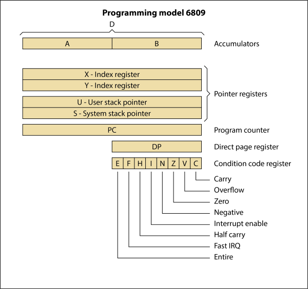
Accumulator registers A, B and D
The accumulator registers (A, B) are general-purpose 8-bit registers used for arithmetic calculations and data manipulation.
Certain instructions concatenate these registers into one 16-bit accumulator with register A positioned as the most-significant byte. When concatenated, this register is referred to as accumulator D.
Index registers X and Y
The index registers are used during the indexed addressing modes. The address information in an index register is used in the calculation of an effective address. This address may be used to point directly to data or may be modified by an optional constant or register offset to produce the effective address.
Stack pointer registers U and S
Two stack pointer registers are available in these processors. They are: a user stack pointer register (U) controlled exclusively by the programmer, and a hardware stack pointer register (S) which is used automatically by the processor during subroutine calls and interrupts, but may also be used by the programmer. Both stack pointers always point to the top of the stack.
These registers have the same indexed addressing mode capabilities as the index registers, and also support push and pull instructions. All four indexable registers (X, Y, U, S) are referred to as pointer registers.
Program counter PC
The program counter register is used by these processors to store the address of the next instruction to be executed. It may also be used as an index register in certain addressing modes.
Direct page register DP
This 8-bit register contains the most-significant byte of the address to be used in the direct addressing mode. The contents of this register are concatenated with the byte following the direct addressing mode operation code to form the 16-bit effective address. The direct page register contents appear as bits A15 through A8 of the address. This register is automatically cleared by a hardware reset to ensure M6800 compatiblity.
Condition code register CCR
The condition code register contains the condition codes and the interrupt masks as shown below.
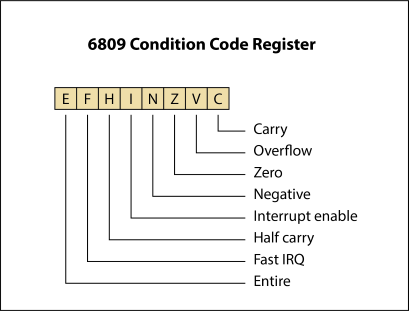
Condition code bits
Five bits in the condition code register are used to indicate the results of instructions that manipulate data. They are: half carry (H), negative (N), zero (Z), overflow (V), and carry (C). The effect each instruction has on these bits is given in the detail information for each instruction.
Half Carry (H), Bit 5
This bit is used to indicate that a carry was generated from bit three in the arithmetic logic unit as a result of an 8-bit addition. This bit is undefined in all subtract-like instructions. The decimal addition adjust (DAA) instruction uses the state of this bit to perform the adjust operation.
Negative (N), Bit 3
This bit contains the value of the most-significant bit of the result of the previous data operation.
Zero (Z), Bit 2
This bit is used to indicate that the result of the previous operation was zero.
Overflow (V), Bit 1
This bit is used to indicate that the previous operation caused a signed arithmetic overflow.
Carry (C), Bit 0
This bit is used to indicate that a carry or a borrow was generated from bit seven in the arithmetic logic unit as a result of an 8-bit mathematical operation.
Interrupt mask bits and stacking indicator
Two bits (I and F) are used as mask bits for the interrupt request and the fast interrupt request inputs. When either or both of these bits are set, their associated input will not be recognized.
One bit (E) is used to indicate how many registers (all, or only the program counter and condition code) were stacked during the last interrupt.
Fast Interrupt Request Mask (F), Bit 6
This bit is used to mask (disable) any fast interrupt request line (FIRQ). This bit is set automatically by a hardware reset or after recognition of another interrupt. Execution of certain instructions such as SWI will also inhibit recognition of a FIRQ input.
Interrupt Request Mask (I), Bit 4
This bit is used to mask (disable) any interrupt request input (IRQ). This bit is set automatically by a hardware reset or after recognition of another interrupt. Execution of certain instructions such as SWI will also inhibit recognition of an IRQ input.
Entire Flag (E), Bit 7
This bit is used to indicate how many registers were stacked. When set, all the registers were stacked during the last interrupt stacking operation. When clear, only the program counter and condition code registers were stacked during the last interrupt.
The state of the E bit in the stacked condition code register is used by the return from interrupt (RTI) instruction to determine the number of registers to be unstacked.
MC6809 Programming manual (PDF, scanned)