Stresses beyond those listed may cause permanent damage to the device. These are stress ratings only and functional operation of the device at these or any other conditions beyond those indicated under “recommended operating conditions” is not implied. Exposure to absolute-maximum-rated conditions for extended periods may affect device reliability.
Electronics
Reading datasheets: Absolute Maximum Ratings
tl;dr;
Always use a current-limiting series resistor when driving a LED from a voltage source.
Reading datasheets of electronic parts is an art you have to learn. It requires analysis and interpretation. Few parts of a datasheet are so often misinterpreted as Absolute Maximum Ratings.
In this video humanharddrive claims that the output current of a 74HC164 is limited to 25 mA. Let's see what the datasheet says:
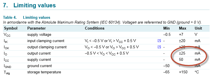
The note at the top says: “In accordance with the Absolute Maximum Rating System (IEC60134)”. Now NXP doesn't say here what is in IEC60134, but it does in other datasheets:
Other manufacturers systematically include this text almost verbatim in the Absolute Maximum Rating section of all of their datasheets.
It means that the 25 mA, which is indeed indicated, is NOT the maximum allowed current for normal operation. Nor is it a current limit observed by the IC, like humanharddrive and others seem to think. The 25 mA is a limit beyond which device damage will occur, and it's the user's responsibility to keep the current below that limit.
How much lower? IEC60134 says you should stick to “recommended operating conditions”. The NXP does indeed have a section named “Recommended operating conditions” (section 8, page 5 of the datasheet ), but that doesn't say anything about currents. This is where the interpretation I mentioned comes in. When we look further into the datasheet we see the following table:
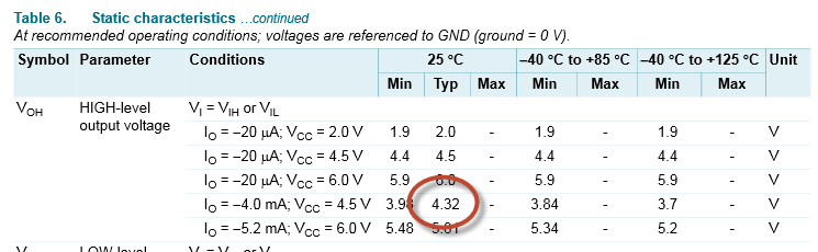
At VCC = 4.5V and 4 mA output the output voltage typically drops 180 mV. This means that the impedance of the output FET in that case is 45 Ω. The maximum voltage drop is 520 mV, which corresponds to a 130 Ω output impedance. Note that no minimum voltage drop is given, so there's also no minimum output impedance.
Let's stick with the value of 45 Ω and assume that this is also the typical value for a VCC of 5 V. Now let's connect a red LED directly and without series resistor to the output pin, like humanharddrive does. A red LED has a typical forward voltage around 2 V, so there will be 3 V across the output FET. 3 V across a 45 Ω impedance is 67 mA. In practice the current will be somewhat lower due to the heating up of the FET, but this is way higher than the Absolute Maximum Rating of 25 mA! While you can probably safely go a bit above the 4 mA from the datasheet (at 6 V they mention 5.2 mA) you should never come anywhere near 25 mA, let alone 67 mA. I repeat, it's your responsibility to keep the current low, by placing a series resistor.
One may be tempted to make the calculation for a white or blue LED, which has a forward voltage drop between 3 V and 3.5 V. And yes, you may find that the current stays below 25 mA. So, it's OK then? No, it isn't. We've used the typical value for the output impedance, and the actual value may be less than that. I've never seen a datasheet which gives a lower limit here. So the current as limited by the FET could always be higher.
Setting an example
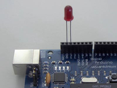
Now humanharddrive no doubt means well, probably just hasn't had proper training in electronics. Possibly, but through this video and similar resources on the 'Net electronics enthousiasts create bad habits. I repeat: it's never OK to power a LED from a voltage source without current-limiting resistor. So I was completely astonished (should I say "shocked"?) when I saw this picture in a workshop by Arduino's Massimo Banzi, from Arduino's original designers core, and former lecturer. Massimo, don't teach people stuff like this! In the ATmega328P's datasheet we see that the output impedance for the ATmega328P is even less than that of the 74HC164: just 26 Ω (Figure 31-355, page 505). Powering a red LED directly, like Massimo does here, will make the FET become extremely hot (those are really small FETs on a die, nothing like discrete power FETs), until it will eventually fail.
By the way, on the Arduino UNO webpage they also mention a DC current per I/O pin of 40 mA (though they don't say whether that's maximum allowed, or internally limited). Once again, that 40 mA is Absolute Maximum Ratings, and you should never on purpose come near that value.
- 74HC164 datasheet by NXP
- ATmega328P datasheet by Atmel
- Arduino UNO characteristics