Electronics
Opamp tutorial
Introduction
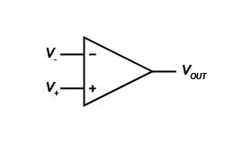
An operational amplifier (opamp) is a building block whose characteristics allow to use it for a number of electronic operations, hence "operational". Below is the opamp's schematic symbol.

The transfer function is defined as $$ \bbox[10px,border:2px solid #383749]{ \large{ V_{OUT} = G \cdot (V_+ - V_-) }} $$ where $G$ is the gain, i.e. the amplification. So an opamp will amplify the difference between the two input voltages.
The ideal opamp is an amplifier with the following properties:
- infinite open loop gain $G$
- infinite bandwidth
- infinite input impedance
- zero input current
- zero output impedance
The voltage follower

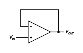
The voltage follower, or unity gain buffer amplifier is the most simple circuit you can make with an opamp. The transfer functions follows from the ideal opamp's transfer function:
$$ \begin{array} {rcl} V_{OUT} & = & G \cdot (V_+ - V_-) \\ V_{OUT} & = & G \cdot (V_{IN} - V_{OUT}) \\ (1 + G) \cdot V_{OUT} & = & G \cdot V_{IN} \end{array} $$
$G$ is the gain, and for the ideal opamp that's infinite. For real life opamps the gain will be a finite value, but still very high: usually somewhere between 100 000 and 1 000 000. Then the term $1$ in the equation is negligible, so that we get
$$ \bbox[10px,border:2px solid #383749]{ \large{ V_{OUT} = V_{IN} }} $$
Note that the actual open loop gain is not important, as long as it's very high. In opamp circuits with negative feedback the open loop gain cancels out.
OK, that's nice, we have an output which is the same as the input. Why would I use an opamp for this? The answer is impedance. Remember that for the ideal opamp the input impedance is infinite, and the output impedance zero. That means that the opamp's input doesn't load the circuit it's connected to, which may be important for high impedance circuits. The low output impedance allows to drive relatively low impedance loads.
An example
Suppose you have a voltage divider which creates a 5 V from 10 V with two 10 kΩ resistors. Now you connect a 20 kΩ load to the 5 V point. Because the 20 kΩ is in parallel with the lower 10kΩ resistor that resistance becomes 6.67 kΩ, and the divided voltage drops from 5 V to 4 V! The solution is to buffer the voltage divider with a voltage follower. Remember that the opamp's input is high impedance, so that it doesn't influence the divider: 5 V remains 5 V. That's also the output voltage, and because the output is low impedance the 20 kΩ load doesn't change it. Problem solved.

next: the inverting amplifier