Electronics
Basic transistor switching circuits
In microcontroller circuits discrete transistors are often used to switch a DC load on and off, like a small lightbulb, a relay or a motor. Until the end of the 20th century this was often done by BJTs (Bipolar Junction Transistors), today more and more MOSFETs are being used. How do they differ?
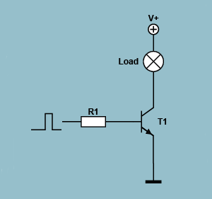
Basic BJT circuit
While BJTs are pretty complex devices to understand completely, they're rather easy to use as switches. The base-emitter junction behaves like a diode, so when forward polarized it will show a 0.65 to 0.7 V voltage drop. Then the base current can be expressed as
$$ I_B = \dfrac {V_{control} - 0.7 V}{R1} $$
or, put differently:
$$ R1 = \dfrac {V_{control} - 0.7 V}{I_B} $$
So, if we know how much base current is required we can calculate \(R1\). For this we need one of the transistor's more important parameters: \(H_{FE}\). That's the current amplification, which defines how much collector current will flow for a given base current. In a formula:
$$ I_C = H_{FE} \times I_B $$
The collector current is the current through the load, and we know the load's characteristics we know that, or can calculate it. Let's assume our load is a 12V/360mW relay. Then \(I_{relay} = \frac{0.36W}{12V} = 30mA\).
For small signal transistors \(H_{FE}\) is typically 100, so that the required base current \(I_B = \frac{30mA}{100} = 300 \mu A \). If we assume a control voltage of 3.3 V (like from a microcontroller) then we can calculate the required value for \(R1\):
$$ R1 = \dfrac {V_{control} - 0.7 V}{I_B} = \dfrac {3.3 V - 0.7 V}{300 \mu A} = 8.67 k \Omega $$
Now \(8.67 k \Omega\) is not a standard value. Do we choose the higher or lower value? If we pick the next higher E24 value, which is \(9.10 k \Omega\), then we might not supply enough base current, and the relay may not activate. A lower value, like \(8.20 k \Omega\) in the E24 series, would increase the base current and therefore also the collector current. Or would it? The relay's coil voltage is \(12V\), its current \(30 mA\), so its resistance is \(400 \Omega \). Then no matter how much current the transistor tries to draw, the coil's resistance will limit it to \(30 mA\). As we'll see later it's even better to have a big safety margin on the base current. When we choose \(R1=510\Omega \) then the base current will be \(5mA\), which is fine for most microcontrollers.
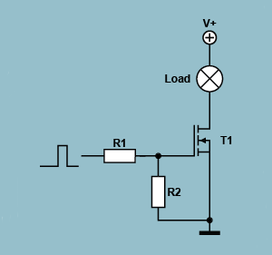
Basic MOSFET circuit
Unlike the BJT, which is current controlled through its base current, a MOSFET is voltage controlled. MOSFETs have been around for quite some time, but only recently began to replace BJTs for these microcontroller switching tasks. The main reason is that only recently MOSFETs can be controlled by the low voltages from microcontrollers, where \(3.3V\) is becoming more and more the standard.
Basically, if you have selected the right MOSFET, you can apply the microcontroller's output voltage directly to the gate. So, why does the schematic on the left have two resistors?
Just like for the BJT, \(R1\) limits the current from the microcontroller. Although the MOSFET's gate is high-impedance, it has a relatively large capacitance, so \(R1\) helps to limit the current peak when switching. Microcontrollers don't like capacitive loads. A value of \(1k\Omega\) is fine.
\(R2\) is related to the high-impedance. This impedance is so high that when the gate is left floating a static voltage can build up that may destroy the FET. Even a \(1M\Omega\) resistor will drain this static voltage to ground, although \(100k\Omega\) is a more typical value. It's worth noting that \(R1\) and \(R2\) form a voltage divider, which reduces the gate voltage. Choosing a (high) value of \(10 k\Omega\) for \(R1\) and a (low) value of \(10k \Omega\) for \(R2\) will halve the microcontroller's output voltage! But with values of \(1k\Omega\) and \(100k\Omega\) the reduction is only 1% and negligible.
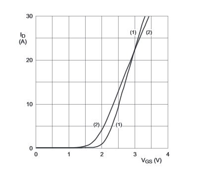
What FET should I choose? Obviously it should be able to handle the load, but at \(30mA\) this shouldn't be a problem. The important parameter here is the threshold gate-source voltage \(V_{GS(th)}\). The graph on the left shows drain current versus \(V_{GS(th)}\) for the NXP PMT21EN , a low \(R_{DS(ON)}\), medium current device. When the microcontroller's voltage is near zero the FET doesn't conduct, while at 3.3 V it's able to sink more than 10 A.
BJT or MOSFET?
So both BJTs and FETs can be used in our relay-switching application. Which one should we choose?
Neither are perfect switches, and both have their specific advantages and disadvantages. Let's start with the BJT.
When used as a switch the BJT has a saturation voltage \(V_{CE(sat)}\). This voltage can range from around 15 mV to around 1 V for common transistors (i.e. non-Darlington). It will only reach its lowest value when there's a lot of base current, much more than the \(H_{FE}\) rule would require. A transistor with an \(H_{FE}\) of 100 may require as much as 100 mA of base current for 1 A of collector current to reach something like 250 mV saturation voltage. 100 mA is a lot more than a microcontroller output can deliver, so why would we want such a low saturation voltage \(V_{CE(sat)}\)? The answer is dissipation.
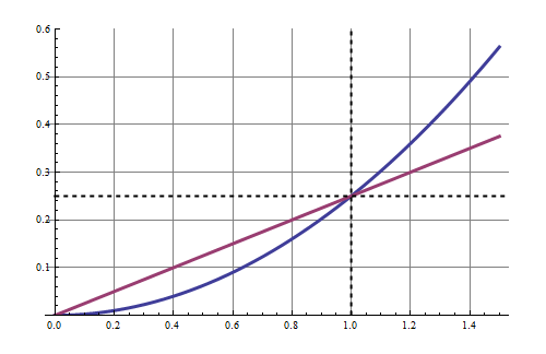
For the FET it's different: this has a fixed ON-resistance \(R_{DS(ON)}\) for a given control voltage. Since power dissipation is quadratic with respect to resistance the dissipation curve will be a parabole, the blue curve in the graph. This one also has a 250 mW dissipation at 1 A drain current, so \(R_{DS(ON)}\) is 250 mΩ.
One thing which is clear from the graph is that at lower currents the dissipation is less for a FET than for a BJT. The curves cross at a current of \(I = \dfrac{V_{CE(sat)}}{R_{DS(ON)}}\). They were arbitrarily chosen such that the curves cross at 1 A. But, while 250 mV is rather OK for a \(V_{CE(sat)}\), an \(R_{DS(ON)}\) of 250 mΩ is nothing special for a FET; there are high-current FETs with \(R_{DS(ON)}\) of 1 mΩ. These are expensive, though, but so are BJTs with low \(V_{CE(sat)}\). Low power MOSFETs and BJTs are comparable in price for the same dissipation.
Conclusion
But we're not done yet. Remember that the BJT needs a lot of base current to drive the transistor into saturation. Even if that's only 10 mA, which most microcontrollers can deliver, the total output current for many of these outputs may exceed the controller's capabilities. That's why the MOSFET is the winner here: in low-power applications it needs nearly zero drive current, and we gladly accept that we need a second resistor.
- datasheet of the BC817 , a BJT capable of switching 500 mA
- datasheet of the PMT21EN , a MOSFET with a low \(R_{DS(ON)}\)