Electronics
RC5
Note:
this is a personal page. I'm not associated with the Philips company, nor am I commercially active in this field.
I'm telling this because in the past I got a few requests I couldn't satisfy, like from companies who want to buy parts from me or who want new codes assigned.
Introduction
RC5 is a remote control (hence "RC") standard devised by Philips. It's pretty straightforward both for encoding and decoding.
Philips and others have been using RC5 for their consumer electronics products for years, so there must be several hundreds of megadevices around by now.
Note: I've seen it referred to as RC5 as well as RC-5. I'll be using RC5 because that's how you'll find it spelled at the Philips RCS site .
It's rather strange then that complete information on RC5 is so hard to find. AFAIK Philips doesn't have a public RC5 spec; you have to check the RC5 component datasheets to get the required information.
If you have any comments, corrections or additions, please let me know.
Data format
Each RC5 code is 14 bits long. A code includes a 5-bit address (or system) and a 6-bit command. This allows for 32 systems (like TV, CD, video, etc.) and 64 commands per system. This is what a standard RC5 code looks like:
where
S1, S2
Start bits: always 1, see text below
T
Toggle bit
A4..A0
Address (or System) bits, MSB first
C5..C0
Command bits, MSB first
The toggle bit T changes each time a new command is transmitted. Its main function is to allow detection of pressing the same key twice. Since a code is being sent as long as the key is pressed, a brief release of the button before it is pressed again would otherwise go unnoticed.
Sixty-four commands per system didn't seem to be enough though, so an extra command
bit was added to accommodate for 128 commands. To maintain compatibility with the standard RC5, the overall format of
14 bits had to be left unchanged, so the second start bit (S2) was replaced by C6.
The resulting format is called Extended RC5.
Now S2 was always “1”, so to make Extended RC5 compatible with standard RC5, C6 is inverted.
Encoding
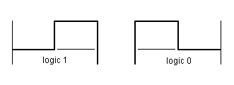
RC5 uses Manchester coding. Manchester always has a transition in the middle of a bit-time as can be seen in the illustration. This allows for easy clock recovery.
Timing
The snapshots below were taken from a (long discontinued) HP (now Agilent) HP54645D 100-MHz 200-MSa/s Mixed Signal Oscilloscope using BenchLink software.
For the following measuments I used an SAA3010, which was a standard IR RC5 transmitter. It's discontinued now; as microcontrollers have become (very) low power they are good replacements for dedicated ICs like the SAA3010.
All timing is derived from a 432kHz clock. A bit time is 3 * 28 clock periods or 1.778ms. A 36kHz carrier frequency can be obtained by dividing the clock by 12.
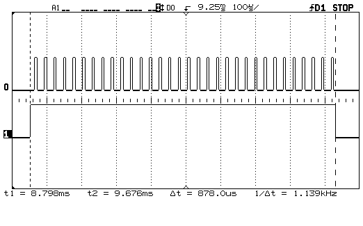
The top channel of each image shows the output on the modulated data output of the SAA3010. The bottom channel shows the baseband data output.
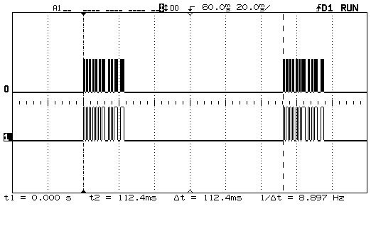
We can see repetition rate is about 9 Hz. This is an ideal frequency to blink a visible light LED on the RC or the receiver.
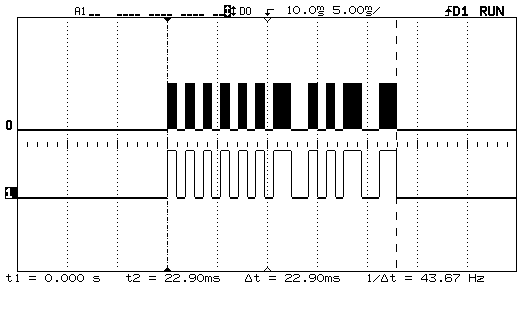
The indicated time of 22.9 ms is in fact a bit shorter than the expected time of 24.89 ms (14 * 1.78 ms). This is because the cursors are wrongly positioned in the middle of the first and last bits, so the measured period is actually 1 bit short.
Even if we wouldn't have known that each code starts with a “1” (low-to-high transition) there is a way to tell where a bit starts. Let's assume that the first rising edge is a bit start. Then in the 7th bit you wouldn't get the mid-bit edge which is required in Manchester coding. So the first rising edge must be mid-bit.
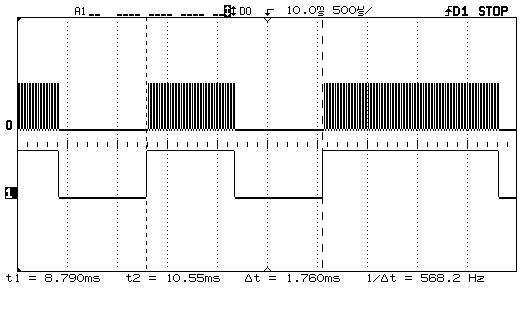
Separate pulses of the modulated data show.
Modulation
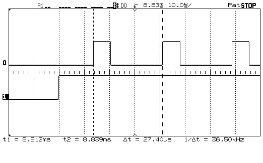
Here you see the duty cycle of the modulated signal is 25%. Newer devices, like the PCA8521 have a programmable duty cycle of 25 or 33%.
This is a good time to calculate the average duty cycle for the IR LEDs: 25% * 50% * 14/64 = 2.7%.
The 50% is the Manchester duty cycle. The 14/64 is the ratio of code bits over a full repetition period.
A peak LED current of 100 mA will therefore result in an average current of 2.7 mA during transmission.
Systems
The 32 systems can be divided into three groups as shown in the table below. I guess all 32 are defined, so additions are welcome.
| 0 | TV1 | 16 | Pre-amp |
| 1 | TV2 | 17 | Tuner |
| 2 | Teletext | 18 | Recorder1 |
| 3 | Video | 19 | Pre-amp |
| 4 | LV1 | 20 | CD player |
| 5 | VCR1 | 21 | Phono |
| 6 | VCR2 | 22 | SAT A |
| 7 | Experimental | 23 | Recorder 2 |
| 8 | SAT1 | 24 | |
| 9 | Camera | 25 | |
| 10 | SAT2 | 26 | CDR |
| 11 | 27 | ||
| 12 | CDV | 28 | |
| 13 | Camcorder | 29 | Lighting |
| 14 | 30 | Lighting | |
| 15 | 31 | Phone |
| Video |
| Audio |
| Other |
Commands
This section has been blank for a long time now, and there's a reason for that. I did start compiling the command tables for the different systems, but in the process I noticed that the RC5 command structure is seriously outdated, and I changed the task to low-priority. You can still find (incomplete) information on the different commands on the Wikipedia page on RC-5.
Alternate use of RC-5.
Like I said RC-5 is being outpaced by recent developments in consumer audio, in particular television. Philips developed RC6 and RC-MM (Multimedia) as successors of RC5 to keep up with the new requirements. RC-6 uses the same modulation scheme and timing as RC5, but the command details are only available under NDA. RC-MM uses a different modulation scheme altogether.
But RC5 is still interesting. I think it's safe to use undefined commands for your own purposes; it's unlikely that RC5 will get developed further. Or you can create a new message structure of your own, even a couple bits longer (or shorter) than RC5's 14 bits. This allows you to use existing encoding and decoding software with only minor changes. Or none at all. You must be careful if you would change the message length or the duty cycle, though: integrated RC5 receivers (see below) are fine-tuned for the RC5 protocol in particular, and especially the AGC may have problems if you would send data continuously, for instance.
Additional information
Special function ICs for encoding/transmitting and receiving/decoding RC5 are getting obsolete. The main reason is that most RC systems are microcontroller-based anyway, so it's cheaper to have the encoding and decoding done by the microcontroller.
I'll still mention some of these older devices (some distributors still have limited stock):
- SAA3010 , an older RC5 transmitter for IR remote controls.
- PCA8521 transmitter is ROM-programmable and therefore less suited for low quantities.
- SAA3049 is an RC5 decoder.
Encoders and decoders are getting replaced with microcontrollers, but there's still need for IR receivers/demodulators. Vishay has a whole range of photomodules with integrated demodulator in different shape SMD and PTH versions.
While RC5 uses 36 kHz as carrier, other frequencies are possible. A number of Vishay devcies are only available for 38 kHz, for instance.
Application Notes:
- AVR410: RC5 IR Remote Control Receiver : Atmel application note describing an AVR based RC5 receiver.
- Decode TV IR Remote Control Signals Using Timer_A3 : Texas Instruments application note for the MSP430.
- Using the Philips 87LPC76x microcontroller as a remote control transmitter : a Philips (now NXP) application note.